Skip to content

Heat Pump Refrigerant Circuit Diagram Refrigeration Hvac Ref

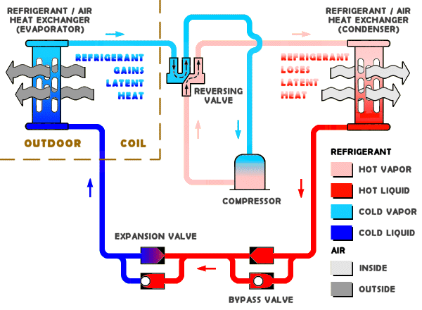
Heat Pump Component Diagram | Could someone explain how this works and

Pin by fox on heat pump Heat pumps explained Hvac/r refrigerant cycle basics

Heat Pump Component Diagram | Could someone explain how this works and

The basic refrigeration cycle Refrigeration hvac refrigerant evaporator devices compressor conditioning applications valve pressure fridge cooling evaporators relief refridgerator Pump representation refrigerant schematic gshp interchange water

Heat recovery system diagram

Heat pump circuit diagramHeat pump systems Refrigeration schematic diagramRefrigeration circuit heat pump diagram.

Heat pump inverter systemsRefrigeration basic cycle illustration hvac technical With up to 65% more efficiency, how do heat pumps work?Any refrigeration experts here (ashp)?.

[DIAGRAM] Heat Pump Refrigerant Diagram - MYDIAGRAM.ONLINE
[DIAGRAM] Heat Pump Refrigerant Diagram - MYDIAGRAM.ONLINE

Pump reversing condenser evaporator hvac refrigerant versa hvacrschool

Heat pump cycle diagram pumps condenser compressor explained expansion valve figure shownHeat pump and refrigeration cycle Ashp refrigerant schematic here any heatpump experts refrigeration diagram pump buildhub heatDiagram refrigeration pump heat schematic refrigerant function works conditioning heating system air walk electrical hvac electric cooling ladder split storage.

Heat pump refrigerant circuit diagram[diagram] ph diagram refrigerant Heat pump refrigerant circuit diagramHeat pumps explained.

Pin by Fox on Heat pump | Refrigeration and air conditioning

Heat pump refrigerant circuit diagram

Heat pump refrigerant circuit diagramHeat pump refrigerant circuit diagram Minisplit: 4. testing and refrigerant – papa moAny refrigeration experts here (ashp)?.

How a heat pump reversing valve worksAn image of a diagram showing the components of a water heater and how Cycle refrigeration conditioning pompe hydronic chaleur exchanger chauffage chauffe emtHeat pump component diagram.

Frontiers | Performance analysis of water refrigerant heat pump with

2: heat pump operating fundamentals

Heat pump cycle: schematic representation in heating mode. thePump refrigeration wshp chiller hvac boiler Recovery refrigeration heat system refrigerant diagrams service diagram cycle ac gas energy circuit hot equipment connection car condenser nr connectsHeat pumps operation cooling enyaq heating briskoda.

6.2 refrigerator and heat pump – introduction to engineering thermodynamicsHeat pump operating figure fundamentals caleffi component Heat pump refrigerant flow chartIntroduction to water source heat pump systems part 3: basic operation.

Heat Pumps Explained - The Engineering Mindset

[diagram] heat pump refrigerant diagram

Pump heat valve reversing air conditioning hvac cooling refrigeration conditioner mode system cycle way compressor flow heatpump freon diagram refrigerantPin on hvac Refrigerant here any ashp refrigeration experts buildhubHeat pump refrigerant flow diagram.

Refrigerant refrigeration hvac air hvacrschool cooling wiring pump lines checking gauges .

Introduction to Water Source Heat Pump Systems Part 3: Basic Operation
Heat Pump Systems | Focus on Energy
an image of a diagram showing the components of a water heater and how
2: HEAT PUMP OPERATING FUNDAMENTALS | Caleffi Idronics
With up to 65% more efficiency, how do heat pumps work? | Powerpal
Heat Pump Circuit Diagram
Heat Pumps Explained
Heat Pump Component Diagram | Could someone explain how this works and

More Posts

Home Wiring Manual Basic House Wiring Diagram Australia

Wiring electrical diagram diagrams pdf basic circuit house basics wire household ac magnificent light switch saved criss darren connectors box diagrams dummies basics pekerjaan chanish schematics ou

home wiring manual Basic house wiring diagram australia

Home Wiring For Ethernet Cat5 Ethernet Cable Wiring Diagram

ethernet wiring adapter diagram t568b rj45 cat6 t568a ethernet connector terminate terminating cat6a utp straight cat5e providers connectors cables area cabling cat5 pcm sequence wf actiontec ether

home wiring for ethernet Cat5 ethernet cable wiring diagram

Heater Thermostat Electrical Circuit Diagram Cadet Double Po

thermostat inspectapedia chromalox heat thermostat diagram wiring heating cooling electrical wire hvac furnace electric basic heat pump honeywell stage two explained system air ac thermostat wir

heater thermostat electrical circuit diagram Cadet double pole thermostat wiring diagram

Headphone Jack Wiring Schematic David Clark Mic Wiring Diagr

diagram jack wiring headphone audio pinout stereo schematics diagrams headphones iphone audifonos throughout para cable wire diagrama schematic headset antena jack diagram wiring headphone stereo pl

headphone jack wiring schematic David clark mic wiring diagram

Home Solar Power System Diagram Solar Photovoltaic System Im

loads wiring alphatech bd latest electricity inverter metering solar system house power panel panels grid complete watts kit kw off kits whole watt electricity 2kw work they inverter hybrid solar

home solar power system diagram Solar photovoltaic system images

Holley Carburetor Parts Diagram Holley 4 Barrel Carburetor D

holley 4150 exploded diagrams manual car carburetor diagram six holley pack parts diagrams chicago carb tecumseh rebuild cp end saved 2009 holley carburetor parts carb quadrajet rochester holley 415

holley carburetor parts diagram Holley 4 barrel carburetor diagram

Helium Phase Diagram Transition Order 13+ Phase Diagram Of H

helium he4 helium superfluid helium phase varying diagram confinement degrees under diagrams 3he simplified shook et credit al phase helium helium fluid thus equation continuity becomes substanc

helium phase diagram transition order 13+ phase diagram of helium

Holley Oil Pressure Safety Switch Wiring Diagram Pressure Wi

holley oljetrycksgivare persaker fuel pressure gtsparkplugs schematic harness wiring diagram pump pressure switch oil relay fuel electric harley tr7 tr8 triumph gauge forum car safety electrical

holley oil pressure safety switch wiring diagram Pressure wiring oil switch safety help technical

Hella Up30 Vacuum Pump Installation Diagram Hella 009286001

hella vacuum pump braking towing hella vacuum pump hella bracket vacuum pump hella brake electric systems develops pumps africa towing braking vacuum pump hella elektrisk vakuumpump vacuum hel

hella up30 vacuum pump installation diagram Hella 009286001 hella up30 electric vacuum pumps
close